You are using an out of date browser. It may not display this or other websites correctly.
You should upgrade or use an alternative browser.
You should upgrade or use an alternative browser.
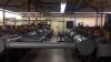
What's the largest trans-match you have ever seen? This may be it.
- Thread starter htperry
- Start date
- Replies 20
- Views 274
9outof10mms
Enginerding, good coffee, and factual opinions.
2A Bourbon Hound 2024
Supporting Member
Multi-Factor Enabled
Not exactly sure what's going on here, but it's making my hair stand up even from this distance. It looks like it could hurt me, bad.
Climberman;n79802 said:This would be a very different thread if drypowder posted it in the basement.
EXACTLY!!! I haven't really looked at the new IDPA rules yet, but I assumed this was related. FlatFender to clarify
htperry;n79857 said:LOL - You guys have tranny on the brain. Ya'll thought this was about a transvestite gun match, didn't you?")
There has to be a reason that Maxpedition makes man purses.
Zedhound;n79955 said:seriously drop some science on us htperry
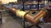
This is probably a medium wave AM antenna tuning unit using a couple of very large copper tubing Variometer style inductors and high voltage vacuum capacitors (1 variable and 3 fixed, in the middle). The loop to the left is most likely for measuring the current through the antenna system. This would be in a station, broadly speaking, of anywhere from 10kw to 100kw. The below examples use fixed inductors rather then Variometers. I thought the OP picture was neat because of the copper tubing Variometers.
Attachments

Last edited by a moderator:
L
Lawless
Guest
Came in here expecting...

cookiecutter
Happy to be here
I, too, thought this was pretty cool ... given that the VV caps are only marginally larger than the ones I use on my small loop antennae for 100W, I'm surprised that this might be for a 10-100kW station ... in any case, I don't think that is a room you'd want to spend time in while that monster was transmitting!
CC
CC
cookiecutter;n80117 said:I, too, thought this was pretty cool ... given that the VV caps are only marginally larger than the ones I use on my small loop antennae for 100W, I'm surprised that this might be for a 10-100kW station ... in any case, I don't think that is a room you'd want to spend time in while that monster was transmitting!
CC
The reason you have vacuum variables on your magnetic loop are for the high voltage rating, more than the current rating. At 100w, your cap is probably overkill on current rating. The caps in the first picture are probably something like 25-50kv @ 500+ amps. Someone here may know better and can say. RFMan
Dang, those VV caps are larger in diameter than a quart mason jar. Never had a datasheet on ones that size.
Yep, for a small loop, the Q is extremely high. Even a 5W QRP loop, efficiently constructed with really low losses everywhere, can generate >1kV at the tuning cap. Small mag loops don't have high current -in the caps themselves-.
Those variometers look cool. They would make a heck of a regen! And that current sampling loop...holy crap.
I went on an afternoon long "private tour" of the VOA station in Greenville (RIP). It was....incredible. A 300kW transmitter is a otherworldly beast.
Paul, I need some eye bleach.... ;-)
Paul, I need some eye bleach.... ;-)
georgel
Behind Every Blade of Grass
Charter Member
Benefactor
Supporting Member
Multi-Factor Enabled
htperry;n79857 said:LOL - You guys have tranny on the brain. Ya'll thought this was about a transvestite gun match, didn't you?
I thought it was about a dating service.
L
Lawless
Guest
JohnFreeman;n80477 said:Paul, I need some eye bleach.... ;-)
I saw large trans and my mind went off in a strange direction...
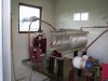
JohnFreeman;n80477 said:I went on an afternoon long "private tour" of the VOA station in Greenville (RIP). It was....incredible. A 300kW transmitter is a otherworldly beast.
I bet the RF combiner room looked something like this? The below pictures aren't VOA, but are of a 200kw site in Missouri City, TX with 9 transmitters combined into the antenna system.