You are using an out of date browser. It may not display this or other websites correctly.
You should upgrade or use an alternative browser.
You should upgrade or use an alternative browser.
Bench grinder electrical question
- Thread starter ACP
- Start date
- Replies 17
- Views 617
That switch appears to be on/off. If want to put a meter on that before wiring it up.
Correct, it’s only on/offThat switch appears to be on/off. If want to put a meter on that before wiring it up.
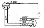
With on/off would the black only be used in wiring the switch,Hope this helps. Typical wiring calls for a black wire for high speed, a red wire for low speed, and the white wire will be the neutral.
A centrifugal switch turns off the starting winding and then the running winding is energized.
View attachment 524582
It might be the wrong switch, the data tag only shows one speed. It might be a two speed motor with the red wire @Button Pusher shows in the wiring diagram.Correct, it’s only on/off
Any thoughts @Scsmith42 ?
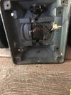
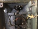
What you said. One wire is probably capped. As old as it is, I’d inspect that cloth covered wire closely for jacket deterioration, especially where it enters the motor housing.It might be the wrong switch, the data tag only shows one speed. It might be a two speed motor with the red wire @Button Pusher shows in the wiring diagram.
Any thoughts @Scsmith42 ?
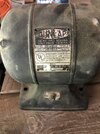
Red and Black can be jumped to the switch, one is the starting winding the other is the running winding. Plate reads 1/4 HP Split Phase.
Split phase motors don't use a capacitor, the motor switches the winding when it gets up to speed with an internal centrifugal switch
Larger single phase motors use start run capacitors, that is what is in most appliances and a/c units.
I have a similar grinder made by Baldor, it is labeled Chicago 3, IL that dates it before the adoption of postal zip codes.
Last edited:
Carolinatlc
Member
2A Bourbon Hound 2024
2A Bourbon Hound OG
Charter Member
Benefactor
Life Member
Multi-Factor Enabled
Same thing I was going to say. Those wires look rough.
Thanks. Wiring would look like black and red from power cord going into switch, black and red from motor to output on switch, white from power cord and switch wired together?Red and Black can be jumped to the switch, one is the starting winding the other is the running winding. Plate reads 1/4 HP Split Phase.
Split phase motors don't use a capacitor, the motor switches the winding when it gets up to speed with an internal centrifugal switch
Larger single phase motors use start run capacitors, that is what is in most appliances and a/c units.
I have a similar grinder made by Baldor, it is labeled Chicago 3, IL that dates it before the adoption of postal zip codes.
711b
Well-Known Member
Unless you're really trying to do this on the cheap, I'd just take it to an electrical motor shop and have them do it AND otherwise check out the motor (no internal shorts, grounding all appropriate, etc.). Otherwise, you might go through a lot of effort and some expense, only to discover there's something else wrong with it -- and that discovery might end up being dramatic and dangerous.
You obviously haven't tested it (or you wouldn't be asking the questions that you are). So another thing you might do -- if you feel comfortable doing it -- is wire it to a supply line without the switch and then use an external switch (or switched outlet) to test it. That would tell you pretty quickly if it is currently in running condition, has a short somewhere, or just won't run for some reason in its internals. THEN take it to an electrical shop.
You might find this posting on vintage Dunlap/Craftsman motors to be interesting. But my sense is that you don't have the experience or tools to dig into this in any real self-repair capacity.
For something like this, I'd really just take to a shop first and possibly save myself a lot of hassle and drama. On the occasions when I've done that, I've been surprised at how little they charge for simple things.
First thing to do would be simple electrical checks using a multimeter.
Measure the resistance from each lead to a bare spot in the metal chassis. Wiggle the wires and hand rotate the motor as you do this. The resistance should be 1 megohm or higher. If it's not, you have a low insulation resistance to ground and that's bad.
Check the lead-to-lead resistance. This will check winding resistance. Here, you're looking for a low resistance, indicating continuity (no broken wires) through the windings. Your running winding will likely be less than one ohm. Your starting winding will be a bit higher in resistance. At any rate, every combination of wire checks should be a low resistance. Rotate the motor be hand when you take these checks: resistances should remain constant.
Given the age, I'd also get some heat shrink and install it over the insulation for each lead. They make it in colors which will match the current lease colors, too.
You motor is 115V so no red on your new grounded power cord. Green to the frame, white to motor white, black to a new switch wire.Thanks. Wiring would look like black and red from power cord going into switch, black and red from motor to output on switch, white from power cord and switch wired together?
Switch wire to motor black and red wire nutted. 😊
711b
Well-Known Member
Really good idea. 👍 I have an old Century Electric oscillating desktop fan (about 10") I bought in some second-hand shop when I was in graduate school and didn't have any money. 😂 50 years later, I still have it and it still works. I think it's from the 1940s (or earlier) and is the type you often see in old detective movies on people's desks. Almost totally silent in operation and the best fan I've ever had. Of course it wouldn't come close to passing safety standards today with its open wire fan cage. And I particularly like the sliding knife switch in it's base.Given the age, I'd also get some heat shrink and install it over the insulation for each lead. They make it in colors which will match the current lease colors, too.
I did have to rewire it some years ago (just the power cord), and using something over that old fabric insulation is necessary. It reminds me of the first house we bought (built in the 1920s): Post and tube wiring in the attic, with decayed fabric insulation. Yikes. Take care with that old stuff.
Last edited:
I got a similar fan in the shop waiting for me to find a “round toit” to fix it up.


